Yesterday was a 'camper' day as I decided to start trying to improve the cosmetics a little.
As is evident in this picture from last year when I was removing the stickers, some paint had lifted off the passenger door. (look carefully in the crease line). As I recall it wasn't on the latest stickers, but some time earlier in the life of the vehicle.
This made the vehicle look tatty, so having located a better door, I went and collected and fitted it yesterday (picture when I manage to download it off the phone). This had the advantage of not waiting for paint to dry and the new door comes off a much newer vehicle so hopefully less time before rust sets.
Sunday, 26 September 2010
Thursday, 23 September 2010
Opto Issues
The issues with the optos are ongoing. I replaced the connection pins with wires on all three my opto circuits, but it appears the one I damaged last time is fubar.
As for the other two:
As for the other two:
- The TechZone optos have the LED enabled until the opto is blocked then it switches off
- On mine, they're never turn off, no matter what I block them with.
Help!!
Tuesday, 21 September 2010
Mendel Mayhem: Completing the bot
Having gotten the X-axis running last time, the job tonight was to finish off the job.
I started by wiring up the Y & Z stepper motors. Luckily with the Zapp Automation stepper motors and the Azdle mounting for my TechZone electronics, I was able to wire the steppers directly, no extending of cables. (The extruder stepper will be another matter).
I then starting playing with moving the axes around using the RepRap host software. This reminded me that I had tweaked the config for the ScrapStrap (which had a belt drive for the Z-axis), so I set about trying to remember how to reset the config. I decided that the best was to get the latest from Sourceforge (now at 20100806 - I had previously installed 201000702).
Upgrading RepRap Host
As I wanted to reset my config, I upgraded as follows:
- Extracted the latest software 20100806 to a temp folder.
- Replaced the raprap.bat with the one I modified last time (to make it work in a different sub-folder)
- Copied in my RepRap.ico file I had created
- Deleted the contents of my install folder (having backed it up)
- Copied in the new installation (and deleted the temp folder)
This means that I reverted by firmware config as well, so I had to reprogram the firmware. This was achieved as follows (any folder locations refer to sub-folders off Reprap\mendel\firmware\FiveD_GCode):
- Copied configuration.h.dist to configuration.h in the FiveD_GCode_Interpreter and Extruder folders (I compared to my old config and was reminded that I commented my changed with my initials - glad I followed a guideline I insist all my coders at work follow)
- Load the FiveD_GCode_Interpreter/FiveD_GCode_Interpreter.pde sketchbook
- Modified the configuration.h tab to match my setup (guessed most of it as I don't know what applies yet - it seems to be pretty much setup for the v3 electronics which the TechZone stuff is - For the hardware, I left it as standard for now, as it should be) and saved.
- Selected the Tools->Board->Sanguino board and then Sketch->Verify/Compile
- Connected the board to the PC.
- Selected Upload to I/O Board and done!!
For the Extruder controller:
- Copied the configuration.h.dist to configuration.h in the Extruder folder
- Moved the USB board to the extruder controller, remembered to invert it (ground is on the opposite side). Mine is now marked with a black marker.
- Loaded the Extruder/Extruder.pde sketchbook.
- Modified the configuration.h tab to match my setup (left it all standard as I didn't see anything relevant to change) and saved.
- Checked the temperature.h tab as I am running a thermistor. I wasn't sure is the default table is correct or not, so I left it be for now.
- Selected the Tools->Board->Arduino Diecimila, Duemilanove or Nano w/ ATmega 168 board and then Sketch->Verify/Compile
- Connected the USB cable to the PC
- Selected Upload to I/O Board and done!!!
- Disconnected the USB and moved it back the main board
Next step, testing the config. I reloaded the RepRap host software and it all worked fine.
Next step was to get on with mounting the end-stops and checking that it can home itself. This is when I discovered one of the issues with the TechZone electronics. In their efforts to reduce the size of the components, they gave no consideration to the retention of the standard mounting locations and as such I managed to damage one of the circuits while trying to make this work. This caused me to suspend work for the evening as I now need to get into some soldering etc, which is a change of focus so will be done on another day...
Sunday, 19 September 2010
Mendel Mayhem: Frame continued
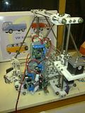
I got bored inside, so here I am again. My wife popped out to the shed to see what was happening, and got a guided tour of the assembly to date.
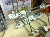
Installing the Y-axis
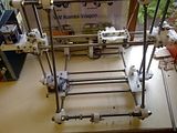
It took very little time to get the Y-axis installed, completed with belt. I then quickly installed the X-axis belt while I thought I knew what I was doing. As said before, the bed is going in later.
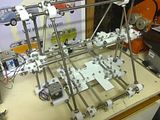
Fitting the electronics
Having a moving cartesian frame and a seperate set of mounted electronics will only drive one insane, so the next step was...
And it works!!!! Well ok, I only connect the X-axis, but at least I'll be able to sleep tonight (sort of).
Installing the Y-axis
It took very little time to get the Y-axis installed, completed with belt. I then quickly installed the X-axis belt while I thought I knew what I was doing. As said before, the bed is going in later.


Fitting the electronics
Having a moving cartesian frame and a seperate set of mounted electronics will only drive one insane, so the next step was...
And it works!!!! Well ok, I only connect the X-axis, but at least I'll be able to sleep tonight (sort of).
Mendel Mayhem: Frame
As I have previously assembled my TechZone electronics on a thick sheet, the next step is the frame.
Frame ends (i.e. the bits that join the two sides together)
Starting to read this I just see that they recommend feet like the ones I fitted. Great minds and all...
That was another hour, I think I'm calling it a day for now. The next step in the instructions is the lower circuits, but that doesn't apply with the Techzone electronics, the next instalment should see the Y-axis, bed and electornics (on the side) installed.
Frame sides
The lower vertex pieces supplied by Nophead have feet so I needed to ensure I took heed of this from the off (I don't know which he used, so no link, sorry These are Nophead's own design, frame-vertex_with_simple_foot_4off located in the alternative-parts repository).
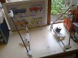
I did a loose assembly initally, but tightened one end of each threaded bar. Then laying the assembly flat on the worktop I adjusted them to the jigged value. For locating the Z-leadscrew brackets, motor bracket & tensioner, it is useful to note that the lying the assembly flat on the worktop allows you to have these pointing up perpendicularly.
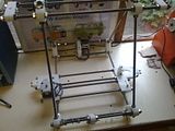
So another hour got me from this:
To this:
I also decided to use these 3M stick on rubber feet that I found somewhere (I'm a bit of a hoarder if you hadn't realised yet). The picture on the right shows one fitted to the Mendel's foot. They should help a bit with regard to the reduction of noise/vibration transmission to the worktop.
Frame ends (i.e. the bits that join the two sides together)
Starting to read this I just see that they recommend feet like the ones I fitted. Great minds and all...
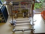
In reality this is the assembly of the main framework (without axes), so quite time consuming with all the calibration. As you'll see if you look carefully at the first picture, I was so happy to be done after 1.75 hours that I had forgotten to align the Y-axes motor and idler brackets.
This is going to be an epic segment as I need to get all the cross pieces in.
On sorting these out I found that my large mudguard washers on the motor bracket were preventing the M8 washer from getting past. Loosening the M4 bolt a bit so the washer could 'wiggle' allowed the two to pass each other. Another 15 minutes had passed, so 2 hours in total for the frame assembly.
X-axis installation
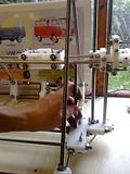
Following the instructions on the 'Mendel Frame' page of the wiki, I noted the following (depicted in the pictures below):
- The cap screws for the Z-lead screw bearings are easier to fasten if they point upwards. The picture will show that I only switch to this for the 3rd screw on each side as the bolts for the Z-bar bracket prevent my socket from fitting.
- The instructions mention that that X-axis should be approximately levelled before adding the belt. I achieved this by using the J3 measuring jig as shown.
- I double checked the spacing of the top brackets by measuring and comparing to the leadscrew brackets at the bottom. (Still need to test full travel).
Mendel Mayhem: Y-axis continued
Chassis
Now that I have the requisite thick sheet parts I'll get on with assembly.I started with the bearing blocks as the template supplied by Nophead for the squashed froglet doesn't have the slotted holes for aligning them. You do the alignment first and then drill the holes accordingly.
Everything seems to line up properly so it went quite quickly in the end (about an hour, with some fiddling about when I had to drill the extra holes, etc).
Mendel Mayhem: Squashed froglet
As stated in yesterday's segment, this morning I tackled the Thick Sheets.
When I finished last night I updated my Reprappers forum topic to update on my progress. Nudel recommended Nophead's froglet made from Dibond (which I have some of as I bought too much in anticipation of making a heated bed and am selling extras). He also told me that the standard thin sheets (opto plates) don't work with the Techzone electronics so saved me some wasted effort.
The standard thick sheet parts comprise:
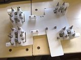
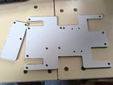
I have already made Azdle's Mounting Plate for Tech Zone Remix Electronics as described here, and will make the bed later as I want to make a heated bed, so this morning I cut up a Dibond FR sheet to make the Nophead's Squashed Froglet and a purge plate as shown below.
That's about another hour, so with that done, I'll be able to continue the Y-axis build, but first I'm off to walk the dogs before it rains (It is still summer - sort of - in England afterall.)
When I finished last night I updated my Reprappers forum topic to update on my progress. Nudel recommended Nophead's froglet made from Dibond (which I have some of as I bought too much in anticipation of making a heated bed and am selling extras). He also told me that the standard thin sheets (opto plates) don't work with the Techzone electronics so saved me some wasted effort.
The standard thick sheet parts comprise:
- Squashed Frog (chassis)
- Purge plate
- Bed
- Electronics mounting plates (2-off)
I went and re-read of Nophead's 'Making Mendel' post to confirm my approach.
That's about another hour, so with that done, I'll be able to continue the Y-axis build, but first I'm off to walk the dogs before it rains (It is still summer - sort of - in England afterall.)
Saturday, 18 September 2010
Mendel Mayhem: Y-axis
I know this one will come to grinding halt soon as I will have to go and make the thick and thin plate parts, but for now, here goes.
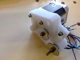
Motor Bracket
As with the Z-axis, fit the pulley to the motor first if you're using the set screw one's.
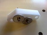
Idler Bracket
The mudguard washers again needed grinding to fit...
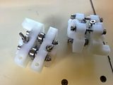
Y bearing 360
Two of these required, mirror images of each other.
Y bearing 180
Two mirrored sub-assemblies required again.
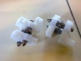
Another 1.5 hours later and next up is the Y-axis chassis, but as mentioned at the beginning of this post, that requires the 'thick sheets'. So I'm stopping here for now and will be cutting thick plates before the next tranche of assembly.
Thanks for watching and good night!
Motor Bracket
As with the Z-axis, fit the pulley to the motor first if you're using the set screw one's.

Idler Bracket
The mudguard washers again needed grinding to fit...

Y bearing 360
Two of these required, mirror images of each other.

Y bearing 180
Two mirrored sub-assemblies required again.

Another 1.5 hours later and next up is the Y-axis chassis, but as mentioned at the beginning of this post, that requires the 'thick sheets'. So I'm stopping here for now and will be cutting thick plates before the next tranche of assembly.
Thanks for watching and good night!
Mendel Mayhem: Z-axis
Leadscrew base & Leadscrew base with optoswitch
As these two are very similar I decided to break into mass production and build them at the same time.
Note, due to my mudguard washers being too large (they are M4 though) I had to grind away a recess to allow them to sit so closely together. I again left the actual circuit board off until later in case of damage.
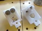
Motor bracket
NOTE: If you're using set screw pulleys then fit the pulley to the motor before fitting the motor to the bracket. Not a big thing, but it does waste timing when you have to remove screws you've just put in.
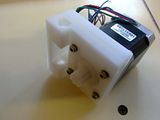
Tensioner
Nothing to say really...
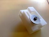
Lead-screw
Mass production again as there are two of these...
The instructions say to remove the pulley again for later assembly hence the dismantled state in the picture. As you can see I have Nophead's Z-pulley's as well.
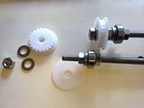
That's all folks
It seems that's the end of the Z-axis for now until the whole unit comes together. That was another 1.5 hours.
As these two are very similar I decided to break into mass production and build them at the same time.
Note, due to my mudguard washers being too large (they are M4 though) I had to grind away a recess to allow them to sit so closely together. I again left the actual circuit board off until later in case of damage.

Motor bracket
NOTE: If you're using set screw pulleys then fit the pulley to the motor before fitting the motor to the bracket. Not a big thing, but it does waste timing when you have to remove screws you've just put in.

Tensioner
Nothing to say really...

Lead-screw
Mass production again as there are two of these...
The instructions say to remove the pulley again for later assembly hence the dismantled state in the picture. As you can see I have Nophead's Z-pulley's as well.

That's all folks
It seems that's the end of the Z-axis for now until the whole unit comes together. That was another 1.5 hours.
Mendel Mayhem: X-axis part 3
I was meant to be out and about sorting out bits for the camper today, but as the guy I was to see wasn't available I decided to make it a Mendel day.
I have added these pictures of the assemblies that I've built to the previous X-axis pages.
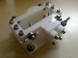
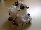
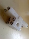
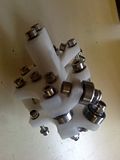
I started the day by spending most of the morning cutting the threaded rod and bar with the cut off saw I mentioned last time.
What I haven't mentioned before is that I am using stainless fittings, threaded bar and rod throughout. This has had the effect of causing the cutting to take much longer as tidying the threads is very difficult.
I decided on stainless as by shopping around I was able to get the bits for not too much more than mild steel (the shipping ends up being an equaliser) and my Mendel will live in the shed so needs as much protection as possible.
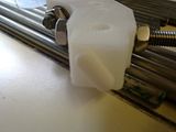
Next step was to quickly calibrate the x-axis carriage as I had to leave that till I had the bar cut. Again I was impressed with the print quality as I did have to do much tweaking to get it sliding smoothly. Having said that I think some more calibration will be in order when the entire unit is assembled.
Motor bracket
My approach to assembly is similar to when I build Meccano. I find all the parts listed, put then in container where I am working and start assembly. As I am following the Wiki assembly instructions I am finding times where the RP parts aren't there. Not because Nophead forgot to include them, but rather because the set he sells includes a number of updates. In this case using the 'Alternate X Motor Bracket'. That's the good thing about buying from someone who is constantly striving for improvement. The downside is that I now realised that my X-axis bars were too long. This bracket needs 463mm bars, not 495mm (oh well, back the garage...). The additional issue with these changes is that they may require fixings not specified in the main BOM. In this case, the stepper motor needs shorted screws than the (shortest) M3x20 caps specified. I went and had a rummage in the binds of screws from scrapped printers, etc and managed to find enough suitable ones.
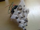
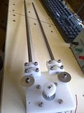
Final x-axis assembly
This step brings the sub-assemblies made before together. There is again a slight twist as the spacers are no longer required with the alternate motor bracket. I decided not to fit the belt at this stage (a decision that make come back to haunt me later) as I felt I would keep knocking it off while fiddling.
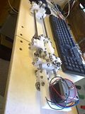
With a lunch interruption, that's been another 2 hours, not counting the cutting time this morning.
I have added these pictures of the assemblies that I've built to the previous X-axis pages.


I started the day by spending most of the morning cutting the threaded rod and bar with the cut off saw I mentioned last time.
What I haven't mentioned before is that I am using stainless fittings, threaded bar and rod throughout. This has had the effect of causing the cutting to take much longer as tidying the threads is very difficult.
I decided on stainless as by shopping around I was able to get the bits for not too much more than mild steel (the shipping ends up being an equaliser) and my Mendel will live in the shed so needs as much protection as possible.
Next step was to quickly calibrate the x-axis carriage as I had to leave that till I had the bar cut. Again I was impressed with the print quality as I did have to do much tweaking to get it sliding smoothly. Having said that I think some more calibration will be in order when the entire unit is assembled.
Motor bracket
My approach to assembly is similar to when I build Meccano. I find all the parts listed, put then in container where I am working and start assembly. As I am following the Wiki assembly instructions I am finding times where the RP parts aren't there. Not because Nophead forgot to include them, but rather because the set he sells includes a number of updates. In this case using the 'Alternate X Motor Bracket'. That's the good thing about buying from someone who is constantly striving for improvement. The downside is that I now realised that my X-axis bars were too long. This bracket needs 463mm bars, not 495mm (oh well, back the garage...). The additional issue with these changes is that they may require fixings not specified in the main BOM. In this case, the stepper motor needs shorted screws than the (shortest) M3x20 caps specified. I went and had a rummage in the binds of screws from scrapped printers, etc and managed to find enough suitable ones.


Final x-axis assembly
This step brings the sub-assemblies made before together. There is again a slight twist as the spacers are no longer required with the alternate motor bracket. I decided not to fit the belt at this stage (a decision that make come back to haunt me later) as I felt I would keep knocking it off while fiddling.

With a lunch interruption, that's been another 2 hours, not counting the cutting time this morning.
Wednesday, 15 September 2010
Mendel Mayhem: X-axis continued
I ordered a Silverline 150mm Metal Cut Off Saw on Ebay yesterday, figuring that I do quite a bit of 'light' metal work and my wood chop saw made a huge difference to my productivity.
So I have decided to further put off cutting the threaded bar and rod until that arrives.
Idler Bracket
So today sees me starting what I can on the Idler Bracket. It's a bit like building some Meccano (Erector set in the US) except the instructions are not quite as step-by-step. In this case, completion awaits the assembly of more sub-assemblies, so on with the next...

Vert bearing 180
Final assembly of this item will also be delayed by thin plate parts (Z-opto flag), but I'm pressing ahead. This came together quite quickly, allowing me to press on to...

Vert bearing 360
This will be the last for the evening. I must say that so far I am really impressed with the print quality of the parts. Then again, I shouldn't be surprised as I made a point of buying them from Nophead (I figured if I was going to buy them I might as well get them from a community acknowledged expert. Well, that also went pretty quickly. I haven't fitted the Opto circuit yet as I don't want to risk knocking it during assembly.

I'm done for the evening (that's about 1.75 hours including numerous interuptions by my 8yr old), will progress again another day....
So I have decided to further put off cutting the threaded bar and rod until that arrives.
Idler Bracket
So today sees me starting what I can on the Idler Bracket. It's a bit like building some Meccano (Erector set in the US) except the instructions are not quite as step-by-step. In this case, completion awaits the assembly of more sub-assemblies, so on with the next...

Vert bearing 180
Final assembly of this item will also be delayed by thin plate parts (Z-opto flag), but I'm pressing ahead. This came together quite quickly, allowing me to press on to...

Vert bearing 360
This will be the last for the evening. I must say that so far I am really impressed with the print quality of the parts. Then again, I shouldn't be surprised as I made a point of buying them from Nophead (I figured if I was going to buy them I might as well get them from a community acknowledged expert. Well, that also went pretty quickly. I haven't fitted the Opto circuit yet as I don't want to risk knocking it during assembly.

I'm done for the evening (that's about 1.75 hours including numerous interuptions by my 8yr old), will progress again another day....
Monday, 13 September 2010
Mendel Mayhem: X-axis
Following the Mendel mechanical construction notes on the wiki, I decided to cheat and not do them in order.
I had been acquiring bits over time so have just about everything I need and I know my electronics work, but I didn't feel like getting in the cutting/grinding/filing mode tonight, yet wanted to make some progress, so I skipped to the Mendel assembly notes section on the wiki and then decided to start with the X-axis.
Carriage
Assembly of the basic carriage unit went quite quickly, but I need to make the 'thin plate' items (opto flags') and cut the bars before I can finalise the piece, so I guess I have to follow the the order of the wiki. That said, now's a good time to go indoors...

(Note to self: Fit Opto flag and calibrate runners for bars once bars have been cut)
I had been acquiring bits over time so have just about everything I need and I know my electronics work, but I didn't feel like getting in the cutting/grinding/filing mode tonight, yet wanted to make some progress, so I skipped to the Mendel assembly notes section on the wiki and then decided to start with the X-axis.
Carriage
Assembly of the basic carriage unit went quite quickly, but I need to make the 'thin plate' items (opto flags') and cut the bars before I can finalise the piece, so I guess I have to follow the the order of the wiki. That said, now's a good time to go indoors...

(Note to self: Fit Opto flag and calibrate runners for bars once bars have been cut)
ScrapStrap Scrapped
Having too many projects on the go meant I wasn't making progress with the ScrapStrap. The Z-axis wasn't working and in the end I decided to bite the bullet and get some RP parts from someone else.
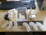
I placed the order and last week a parcel arrived containing an intriguing collection of plastic bits. I'm still amazed and how great these bits are considering they're printed on a home made machine.
Over the next few weeks I hope to assemble my Mendel, and will attmept to keep notes of how I figured out what I was doing.
Camper Part 33: Quick update
Progress has continued on the camper, albeit at a slowish pace.
Since the last post I have refreshed the MOT. The was initially a failure on the fog light switch being loose (I was due to pick up a replace dash the following day so took a chance) and the number plate lights.
These lights are located on the fold out step and wired via brass/copper contacts that only make a connect when the step is folded away. As the step is quite worn the contact is hit and miss. The was on a Saturday so the tester gave me 2 hours to go away and rectify the two problems. The fog switch problem I resolved my knocking up a plywood insert for the dash in place of the broken plastic, whereas I ripped out the contacts and ran folding loom in for the steps. I know this isn't ideal but I intend to replace these steps with a proper motorhome type fold out set which should be much lighter (not being engineered for stretchers, etc).
I also managed to fit all the cupboard doors, the cooker and fridge (they've been in before, but are now in their final fix). The only remaining item on the cupboards are the shelves (simple 3mm ply planned) and the drawer which I need to make and fit.
I also sourced an ex caravan bedframe to make the junior over seat bed in the cab and pieces of another double front seat to allow me to add a second seatbelt to the twin rear seats.
My current focus is on items which prevent use of the vehicle as opposed to the nice to haves. This isn't stopping the collection of usefull bits though.
The vehicle has also seen some use on the road with trips varying from 400 miles one day to around 80 a few times for localish trips.
I had a problem on one of the trips when the valve on one of the wheels failed, luckily on a small road with a handy layby ahead. Only problem I still hadn't sourced a spare (it came with none). If anyone knows where I can get a 15 inch twin wheel Sprinter wheel cheap (don't care about the tyre), please shout.
That's all for today....
Subscribe to:
Posts (Atom)

