Frame sides
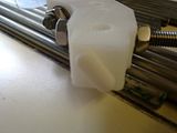
The lower vertex pieces supplied by Nophead have feet so I needed to ensure I took heed of this from the off (I don't know which he used, so no link, sorry These are Nophead's own design, frame-vertex_with_simple_foot_4off located in the alternative-parts repository).
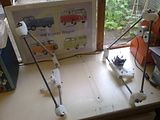
I did a loose assembly initally, but tightened one end of each threaded bar. Then laying the assembly flat on the worktop I adjusted them to the jigged value. For locating the Z-leadscrew brackets, motor bracket & tensioner, it is useful to note that the lying the assembly flat on the worktop allows you to have these pointing up perpendicularly.
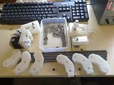
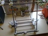
So another hour got me from this:
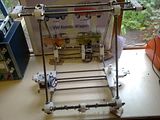
To this:
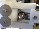
I also decided to use these 3M stick on rubber feet that I found somewhere (I'm a bit of a hoarder if you hadn't realised yet). The picture on the right shows one fitted to the Mendel's foot. They should help a bit with regard to the reduction of noise/vibration transmission to the worktop.
Frame ends (i.e. the bits that join the two sides together)
Starting to read this I just see that they recommend feet like the ones I fitted. Great minds and all...
In reality this is the assembly of the main framework (without axes), so quite time consuming with all the calibration. As you'll see if you look carefully at the first picture, I was so happy to be done after 1.75 hours that I had forgotten to align the Y-axes motor and idler brackets.
This is going to be an epic segment as I need to get all the cross pieces in.
On sorting these out I found that my large mudguard washers on the motor bracket were preventing the M8 washer from getting past. Loosening the M4 bolt a bit so the washer could 'wiggle' allowed the two to pass each other. Another 15 minutes had passed, so 2 hours in total for the frame assembly.
X-axis installation
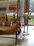
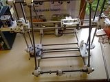
Following the instructions on the 'Mendel Frame' page of the wiki, I noted the following (depicted in the pictures below):
- The cap screws for the Z-lead screw bearings are easier to fasten if they point upwards. The picture will show that I only switch to this for the 3rd screw on each side as the bolts for the Z-bar bracket prevent my socket from fitting.
- The instructions mention that that X-axis should be approximately levelled before adding the belt. I achieved this by using the J3 measuring jig as shown.
- I double checked the spacing of the top brackets by measuring and comparing to the leadscrew brackets at the bottom. (Still need to test full travel).




Hi Craig,
ReplyDeleteLooks like you are making very good progress there. It took me a lot longer to make mine.
The vertex with feet are my own design, you can find them here: http://reprap.svn.sourceforge.net/viewvc/reprap/trunk/mendel/mechanics/solid-models/cartesian-robot-m4/printed-parts/alternative-parts/
Also Vik Olliver did a design with a more complex foot, but I found the holes to be too big.
Thanks nophead,
ReplyDeleteI think it helps that I have been collecting parts for ages (i.e. living the dream). So I had everything in a drawer waiting for assembly.
i've updated the post above to reference your feet.
I'd also add, that this is my de-stressing activity, and it's been a hectic week at work with servers crashing, etc, so I needed this...
ReplyDelete