
Having too many projects on the go meant I wasn't making progress with the ScrapStrap. The Z-axis wasn't working and in the end I decided to bite the bullet and get some RP parts from someone else.
I placed the order and last week a parcel arrived containing an intriguing collection of plastic bits. I'm still amazed and how great these bits are considering they're printed on a home made machine.
Over the next few weeks I hope to assemble my Mendel, and will attmept to keep notes of how I figured out what I was doing.
Showing posts with label ScrapStrap. Show all posts
Showing posts with label ScrapStrap. Show all posts
Monday, 13 September 2010

Tuesday, 20 July 2010
Tech Zone Techniques - Part 4
Step 10: Wiring the steppers
Not much to go wrong here really, as I had wired the stepper sup to my CNC stepper boards before, I kind of knew what I was doing. I also made up a power lead which I have wired up to my variable bench supply for now. (This will be replaced with a PC based ATX supply for the final version).
Step 11: Testing Times
Next up was testing the electronics. I tracked down the Testing RepRap Electronics page on the wiki and started following that through.
I ran into some trouble with the motherboard not returning any temperature results and not looping, so I asked on the forum. In summary, note the following when using the hardware:
- If you don't get the temperature readings looping, then your USB cable may not be autoresetting the hardware
- Plug in the the USB
- Hit the rest button
- Start up the host software
So, I managed to get the desired results for the motherboard and the extruder controller (sans stepper driving), so I decided to move onto to testing the stepper boards and opto's.
For the steppers I followed these steps (for each axis - results further down) (BTW: follow these steps at your own risk, the wiki steps are more detailed and isolate issues, I already knew my steppers work):
- Wired the stepper to the controller
- Ensured the stepper was in the middle of the axis (as I wouldn't know which way it would travel)
- Wired the power to the stepper board
- Wired the stepper board to the motherboard
- Connected the USB
- Reset the motherboard
- Opened the RepRap Host
- Changed to the XYZ tab, and set nudge to 10mm and feedrate to 300mm/min
- Switched on the power
- Clicked the right arrow (>)
- Clicked the left arrow (<)
- Moved on to testing the Opto's
Y-Axis results
- I did the Y-Axis first as it made sense in my wiring config
- > caused a small movement (and was repeatable)
- <>
- Off to the forum to figure out what's wrong (read about this before somewhere)
- Ah... Seems I got the Opto connected the wrong way around. The picture wasn't very clear (that's my story and I'm sticking with it).
- While fiddling with this I noticed that the opto LED (which on the TechZone boards is normally on) was not switching off when blocked.
- I swapped out the other opto's and found that 2 of my three boards had the same problem.
- I've been trying to stay out of the TechZone flaming that's been happening on the forum (I won't post any links, searching for TechZone will find many), but I do think the quality of the soldering leaves something to be desired. I spent a lot of my spare cash with them (it's the single biggest purchase in my project) and wasn't too impressed. I reckon could do it neater and I only tend to solder copper pipes for plumbing and automotive wiring.
- Anyway, off to figure out how to fix my opto's (given I know next to nothing about electronics, this will be interesting).
Following on from the Y-axis, I had mixed results with the others. I eventually figured out that I had to tweak the pot on the stepper boards to get the steppers running properly. I turned them anti-clockwise a bit at a time until they didn't work and then back a bit till they did again.
I then found that my Z-axis motor would run great when the belt was freed off, but wouldn't run the axis. I have just located a more powerful motor on my scrapheap as my Z-axis doesn't even have the extruder mounted yet. (May have the go the bowden route).
Current state of play is X & Y axes work. Z-axis being fiddled with....
Wednesday, 14 July 2010
Tech Zone Techniques - Part 3
Following on from Part 2, I'm still trying to get my electronics moving in the right direction.
Step 9: Loading the firmware (still....)
During the last post I was trying to load the firmware and got an error not in sync...
I searched the forum and found this post. Reading through it I saw the following line "Wrong serial port in use for USB connection", and thought "I didn't set the serial port, so how will it know?", obviously it didn't. The Arduino IDE was set to COM1, not COM5 as it needs to be on my system.
I changed that and hit the upload button. Done in seconds. Boy was that dumb... 3 days of wondering what I did wrong (ok, I didn't come back and work on it for the 3 days as I was doing other stuff, but it still bugged me).
Ok, onwards and upwards, lets program that extruder, here are the steps followed:
- I had already copied the configuration.h.dist to configuration.h in the Extruder folder
- Moved the USB board to the extruder controller, remembered to invert it (ground is on the opposite side.
- Loaded the Extruder/Extruder.pde sketchbook.
- Modified the configuration.h tab to match my setup (left it all standard as I didn't see anything relevant to change) and saved.
- Checked the temperature.h tab as I am running a thermistor. I wasn't sure is the default table is correct or not, so I left it be for now.
- Selected the Tools->Board->Arduino Diecimila, Duemilanove or Nano w/ ATmega 168 board and then Sketch->Verify/Compile
- My board was still connected to the PC from 2 above
- Selected Upload to I/O Board and it worked!!!
- Disconnected the USB and moved it back the main board
At this point I'd had enough for the day and decided to call it quits. Part 4 will start with wiring up the steppers, connecting some power and some ground lines as mentioned above.
Sunday, 11 July 2010
Tech Zone Techniques - Part 2
Following on from Part 1, I'm continuing to try to get my electronics moving in the right direction.
wTo page says if you have 2 pins next to the serial connector you can put a jumper on them for the board to be powered from the USB connection. (In the recent versions of Techzone remix electronics sets sold from Ebay - May 2010).
avrdude: stk500_getsync(): not in sync: resp=0x00
avrdude: stk500_disable(): protocol error, expect=0x14, resp=0x51
More in Part 3...
Step 5: Upload Firmware (or more accurately, installing the Arduino/Sanguino software on my PC)
According to the HowTo page, the boards come with the Makerbot firmware installed. This means that a boot-loader doesn't have to be installed, but the firmware must be updated. This is a new area for me. I am a software developer by trade, but for Windows, not embedded so haven't had to do this before.
I found the Microcontroller firmware installation page on the wiki, so started by following those steps and installed:
- the Arduino software (release 0018);
- Download the zip;
- Extract and move to your desired location;
- Create shortcut (if you want) - I'm waiting till I figure out how to run it.
- followed by Zach's Sanguino extensions.
- Download the zip;
- Extract and move the Sanguino folder into the Arduino/hardware folder.
Before actually programming the boards, you also need to download the latest stable release of the firmware. This is located in the reprap-mendel-yyyymmdd.zip that is installed when installing the Reprap Host software. Guess that means a quick side track. Don't go away.
Step 6: Install Reprap Host Software
Following the instructions on the 'installing the Reprap Host software' wiki page, I did the following (bear in mind that I am starting with a relatively fresh XP installation on the machine I am using for this):
- Installed Java 6 from http://java.com/
- Installed the RepRap Host software from sourceforge (reprap-mendel-20100702.zip)
- Quite easy really, unpack the zip to a suitable location and run the reprap.bat to run the software.
- As I decided not to install in Program Files, I had to edit the batch file. The instructions don't mention this, even though they word it as if installing in Program Files is optional. (I might go edit the wiki if I can figure out how).
- Check out which other Useful Software Packages you need.
Ok, that means I now have the firmware needed to continue with setting up the electronics.
Step 7: Wiring wonders & woes
This forum post by rhmorrison refers to faulty soldering almost blowing his electronics, but more importantly, he describes that moving the stepper motors before powering the electronics will like up the corresponding LED (kind of like the electric motor light bulb generator we all made as kids).
Because of this I decided to do the inter board wiring before hooking up any power to the boards. There seems to be no one clear description and image of this all working. I referenced the following:
- Nudel's ground pin image. (Shows the stepper to main board connections).
- The Tech Zone Official Electronics Installation Page. (Shows the extruder controller to main board connections)
- The Tech Zone HowTo page.
For what it's worth my LED's all lit up when tested by moving the stepper back and forth.

For what's it worth, I will be changing the I2C wiring (one of the 2 wire connectors between the main board and extruder controller) to include a ground wire following Mdbaughman2's experiences.
Step 8: Getting connected
The Ho
On my board, there is what would appear to be two pins that have been permanently shorted/bridged, there are also no connectors for external power, so I figured the board is permanently configured to be USB powered (don't know what this means for using the SD card slot then). Anyway, I figured the best was to give it a go.
Having kept the Arduino Getting Started w/ Arduino on Windows page open since installing the software, I followed the steps on there. Basically the following:
- Plug in the USB connector to your PC;
- When prompted for drivers point to your Arduino/drivers folder (or check the FTDI site for newer ones);
- Open the Arduino application, and revert to the Microcontroller firmware installation instructions (see next step).
Step 9: Loading the firmware (eventually)
I could eventually continue following the steps under the Programming the Motherboard heading on the Microcontroller firmware installation page.
I followed these steps (any folder locations refer to sub-folders off Reprap\mendel\firmware\FiveD_GCode):
- Copied configuration.h.dist to configuration.h in the FiveD_GCode_Interpreter and Extruder folders
- Load the FiveD_GCode_Interpreter/FiveD_GCode_Interpreter.pde sketchbook
- Modified the configuration.h tab to match my setup (guessed most of it as I don't know what applies yet - it seems to be pretty much setup for the v3 electronics which the TechZone stuff is - For the hardware, I left it as standard for now, but will need to change when I figure out the steps, etc on the ScrapStrap) and saved.
- Selected the Tools->Board->Sanguino board and then Sketch->Verify/Compile
- My board was still connected to the PC from Step 8. (if your's isn't, reconnect now).
- Selected Upload to I/O Board and ... It fails!!
avrdude: stk500_getsync(): not in sync: resp=0x00
avrdude: stk500_disable(): protocol error, expect=0x14, resp=0x51
More in Part 3...
Wednesday, 7 July 2010
Plastic Phantastic
Just a quick note tonight. While trying to figure my way through the electronics I figured I needed to also get a move on with the extruder parts.
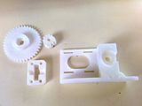
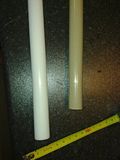
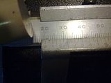
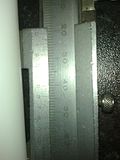
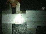

I decided to give in and do the sensible thing, so instead of trying to make an extruder manually I bought a set of RP parts for a Wade's extruder from NopHead of Hydraraptor fame. This is fitting as the heater portion will be based on his Plumbstruder design.
The parts arrived today and are fantastic. These are the first printed parts that i have seen and touched physically, and they definitely inspire me to continue on this quest. Having said that, progress is likely to slow over the next few weeks due to work commitments and holidays.

Here are some pictures of the bits and progress so far (more detailed descriptions will be included in a future post on the plumbstruder - you'll also see that I now have the proper stand-off's for my electronics):


Saturday, 3 July 2010
Tech Zone Techniques - Part 1
Having completed the ScrapStrap hardware, I figured it was time to dig out the Tech Zone Remix electronics that I bought (I bought directly from Kimberly at Tech Zone, but you can now buy them from BotMill)
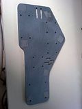
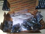
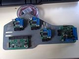
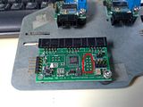
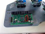
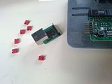
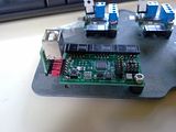
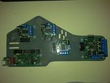
There is a HowTo page on the wiki which I hope to help update, but thought I should keep a record of what I do, as I do it so that I can be sure what works and doesn't. Hence this page. I will be including pictures as I go. This page does not intend to replace the HowTo page or other resources, but should rather be seen as a record of the steps I followed.
Step 1: Mounting plate
Choose and make a mounting plate. As per the HowTo page, these electronics are so much smaller that they don't need to use that original thick sheet. Choosing and making the plate at this point means that you can make the wire lengths to suit.
I chose to go with Azdle's Mounting Plate for Tech Zone Remix Electronics, although in my case it was manually made using my bandsaw and drill press. I installed Inkscape in order to be able to print the svg file out to scale.
The material was a piece of ABS plastic which had formed part of the cover of a plan printer which I stripped recently. I kept the plastic covers in case I could recycle the ABS at some time in the future.

Step 2: Unpack and mount
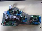
Unpack the the electronics (be careful of static). The first picture was taken removing the bubble wrap, but while still in the anti-static bags. Mount all the pcbs on your mounting plate. (I don't have enough stand-off's so will only complete assembly when I have bought some more. I mocked it up in the meantime)


Step 3: Ground points
Mark the ground pins on all the connectors (see this image). At this point a slight diversion happened as I noted that one of the 10 pin connectors was not in place on the main board. I emailed Tech Zone, but as I didn't feel like waiting to find out if there was a reason for it to be missing I went ahead and fitted one (before and after pics below). I salvaged the connector off an old PC motherboard I had lying around for just such a reason. When de-soldering these I find the best strategy is to remove the plastic bit first and then de-solder one pin at a time. The connector can be reassembled again afterwards.


Step 4: USB/TTL Board to Mainboard connection
Here I followed the lead of those who had gone before and decided to use The Jumper Technique. Instead of creating a cable for linking the USB board, simply use 6 jumpers. This needs the jumpers that have holes right through. I scrounges some of the old motherboards and bits that I have lying around. I'll probably change this to a wired connector in the future once I can print a USB mounting block in order to ensure a firm mounting.


Step 5: Upload Firmware
According to the HowTo page, the boards come with the Makerbot firmware installed. This means that a boot-loader doesn't have to be installed, but the firmware must be updated. This is a new area for me. I am a software developer by trade, but for Windows, not embedded so haven't had to do this before. I'll be continuing with a detailed breakdown in Part 2
Tuesday, 29 June 2010
Adding Axes
To start with, I have come to realise that other people refer to the bed as the Y-axis and the gantry as the X-axis. (No such confusion about the vertical axis which all agree is the Z-axis). To this end, I have gone and updated my previous posts.
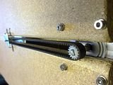
I started with the X-axis drive system (pic 1) and mocked up the Z-axis location (pic 2) and the drive system (pic 3). This made me realise I needed to add spacers to the X-axis rails as the drive system need more space (pic 4):


I then created a mounting plate for the Z-axis, and fitted the X-axis drive. As you can see from the pictures, this is pretty much as removed from the printer, but I cut down the cartridge holder to make a flat surface which could easily be attached to the Z-axis mounting place. I then realised that the (wide) mounting plate (pic 1 below) was fouling on the drive system so I made up a new narrower one as seen in the second pic below. Looking carefully this pic also shows that I had to notch the side of the gantry to get the stepper motor to clear.
The 3rd pic shows how I bent down the X-axis rail end stops to allow the rails to travel in both directions. This means that I could center the Z-axis on the rails. I guess this might come to haunt me in the future as it means I need clearance on both sides of the ScrapStrap, when working, but at least it is less clearance (breathing room) than single sided movement:


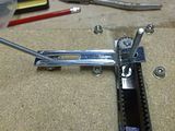
The next step was to mount the Z-axis and it's drive mechanism. This bit was quite fiddly and changed along the way so I didn't take lots of pictures in the middle but did of the end result. Bottom line is that I stripped down another ink jet cartridge drive mechanism and used the stepper motor, drive belt, cut down cartidge holder and spring loaded belt tensioner. The most fiddly bit was to align all the elements so that the belt would grip properly.
The 1st picture shows how I used a single bolt at the bottom and two at the top. This would allow fine adjustment of the 'verticality' of the axis in the X-plane. The 2nd picture shows the initial mockup of the drive train.
The 1st picture shows how I used a single bolt at the bottom and two at the top. This would allow fine adjustment of the 'verticality' of the axis in the X-plane. The 2nd picture shows the initial mockup of the drive train.
The black bit that you can see in the 3rd picture is the cut down cartridge holder, while the bolts are there to attach this to the Z-axis.


These last two pictures show the X & Z-axes completed and mounted on the Gantry. there are two picutres to show the travel in the X and Z directions.


In these pictures the Gantry is not yet mounted to the Y-axis base as I need to ensure that I get this perpendicular. I'm still debating how to ensure this and how accurate it needs to be.
There are 3-planes in which the perpendicularity needs to be ensured. For the X-plane of the Z-axis I have built some adjustment in the Z-axis mounting. The other 2 planes are:
Any comments????
There are 3-planes in which the perpendicularity needs to be ensured. For the X-plane of the Z-axis I have built some adjustment in the Z-axis mounting. The other 2 planes are:
- The X-axis in the Z-plane (i.e. the gantry tilting back and forth); and
- The Y-axis in the X-plane (i.e. the gantry tolting left to right).
Any comments????
Thursday, 24 June 2010
Belting the Bed (Y-Axis)
Not too much to report today after the mega progress on day one.
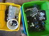
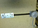
I had a little dig around the bins of printer parts I salvaged and managed to locate a decent looking stepper motor as well as belt and pulleys of the correct size.
Here's a pic of a couple of my bins (I have more):

I had to remove the original pulley from the stepper (hope I didn't damage it in the process) and file a flat on the shaft.
This was all pretty fiddly work as I had to figure out what to do and had to attempt some of the brackets multiple times to get them right. The pics below show the sequence of fitting the stepper, pulleys, belt and finally the bed:


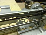
That's all I got done for now, but I thought I would also show you the pics of the two inkjet print head carriages that I dug out and plan try to use for the X & Z axes. The motors are quite light so not sure if they can handle it, but what is nice is that they come with pulleys and belts. I guess only time will tell.


Monday, 21 June 2010
ScrapStrap (a RepRap BootStrap AKA RepStrap)
For those reading I'm back!! a few days ago and wondering about the RepRap, here is a bit more information.
I'm not going to repeat what is available in the RepRap.org wiki, but will paraphrase as a quick introduction.
The RepRap is an open source project to create a self-replicating 3d-printer affordable for the masses. At it's simplest 3d-printer is the type of 'printer' which prints melted plastic into 3d shapes. The current incarnation is the Mendel. All of the plastic parts can be printed on another RepRap or similar, whereas the metal parts, electronics, motors and fixings have to be bought (these are known in the community as vitamins).
The problem lies when you don't have your own RepRap or ready access to one to print the parts for your first Mendel. This is when you have to build a bootstrap device (referred to as a RepStrap). This is a machine which can print in plastic like the RepRap/Mendel, but isn't self replicating. Almost every builder comes up with their own interpretation on this, with some users actually creating very sophisticated systems (see Hydraraptor for an interesting build).
Over the last 3 or 4 months I have been slowly acquiring all the bits to assemble a Mendel, with the plastic now being the main remaining part. I was temped to build an OverlapStrap as built by Giles Bathgate. This attempts to use the same 'vitamins' but with temporary replacement parts for the plastic items. While researching this and deciding what to do I realised that it was difficult to figure out the dimensions of the plastic parts using the drawings and Sketchup. When I posed some questions on the forum yesterday, I was reminded that the WolfStrap would be a good starting point.
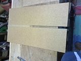
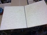
The WolfStrap is a typical Gantry type CNC cartesian bot which can be simply made with DIY materials. Last night after dinner I decided to get started so made off into the garage. Looking at my collection of raw materials (I have lots and odds and sods as I am a bit of a DIY hoarder. I always think I can use something again), I came up with the following:
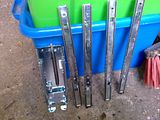
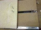
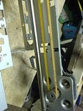
Dell monitor mechanism is quite intriguing as it comprises a set of mini drawer slides, some bracketry and a spring, string, pully and friction brake mechanism design to overcome the weight of the monitor. It even has 15" and 17" markings imprinted for calibration. I have some more detailed pictures here:
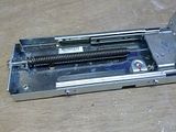
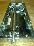
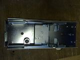
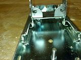
The last two of these are with the weight mechanism removed. I couldn't see the benefit for a RepStrap on which the extruder should be quite light. Probably useful for a mil, but then the 90mm travel will become a limiting factor.
According to the forums, the highest Mendel part is around 30mm, so the 90mm travel that this part will give me should be ample.
The build
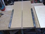
I layed the one chipboard base flat and fitted one of the draw rails on the face but right against the edge so that it extends backwards. Making sure it was straight relative to the edge of the base I screwed it down and then fitted the second rail to the opposite side. For this one I fitted one screw then carefully measured to make sure it was parallel to the first and fitted a second screw to lock it in place.
The rails I used have tabs which could be used for locating the deck/base (Y-axis), so I then took the piece of countertop, carefully measured and cut it to fit between the tabs. Before screwing it down I double checked that it moved freely back and forth to ensure that the rails were really parallel.
The next step was to make up the gantry. Before starting I took a closer look at the monitor mechanism and realised that if I cut the excess off it, then I would get better clearance without having to make up a long bracket for the extruder. I timmed it off level with the ends of the rails (see the later pictures for clarity).
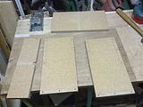
I then eyed out the second piece of chipboard and figured out that it could be cut into 4 pieces to make the front, back and sides of the gantry. As the two pieces of chipboard were square and indentically sized, this means that the 2 pices cut for the front and back match the width of the base. Fitting the sides to the outsides will square things up nicely.
When cutting the front section, I measured the cutdown Z-axis and used this as the size. The length of the sides was determined by the slot which existed in the piece of chipboard and what was left made up the rear section. I then finished off the gantry frame by screwing and gluing the 4 pieces together.
This is best illustrated by some pictures:
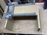
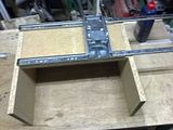
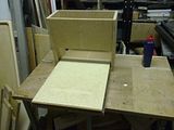
The X & Z axes are just mocked up the picture as is the location of the gantry.
I decided to call it a day at this point as the next step involves two intricate bits of work:
The WolfStrap is a typical Gantry type CNC cartesian bot which can be simply made with DIY materials. Last night after dinner I decided to get started so made off into the garage. Looking at my collection of raw materials (I have lots and odds and sods as I am a bit of a DIY hoarder. I always think I can use something again), I came up with the following:
- The name for my RepStrap - ScrapStrap (as it is made of scrap).
- Two sets of drawer runners from an old flatpack filing cabinet.
- A small sliding mechanism removed from an old Dell PC/Monitor stand. It was designed to allow the vertical height of the monitor to be adjusted.
- The 'legs/base' of an old chipboard occassional table (This is type where two rectangular wooden sections with slots it slide into each other to form a +).
- A small piece of lightweight caravan worktop


Dell monitor mechanism is quite intriguing as it comprises a set of mini drawer slides, some bracketry and a spring, string, pully and friction brake mechanism design to overcome the weight of the monitor. It even has 15" and 17" markings imprinted for calibration. I have some more detailed pictures here:


The last two of these are with the weight mechanism removed. I couldn't see the benefit for a RepStrap on which the extruder should be quite light. Probably useful for a mil, but then the 90mm travel will become a limiting factor.
According to the forums, the highest Mendel part is around 30mm, so the 90mm travel that this part will give me should be ample.
The build
I layed the one chipboard base flat and fitted one of the draw rails on the face but right against the edge so that it extends backwards. Making sure it was straight relative to the edge of the base I screwed it down and then fitted the second rail to the opposite side. For this one I fitted one screw then carefully measured to make sure it was parallel to the first and fitted a second screw to lock it in place.
The rails I used have tabs which could be used for locating the deck/base (Y-axis), so I then took the piece of countertop, carefully measured and cut it to fit between the tabs. Before screwing it down I double checked that it moved freely back and forth to ensure that the rails were really parallel.

The next step was to make up the gantry. Before starting I took a closer look at the monitor mechanism and realised that if I cut the excess off it, then I would get better clearance without having to make up a long bracket for the extruder. I timmed it off level with the ends of the rails (see the later pictures for clarity).
I then eyed out the second piece of chipboard and figured out that it could be cut into 4 pieces to make the front, back and sides of the gantry. As the two pieces of chipboard were square and indentically sized, this means that the 2 pices cut for the front and back match the width of the base. Fitting the sides to the outsides will square things up nicely.
When cutting the front section, I measured the cutdown Z-axis and used this as the size. The length of the sides was determined by the slot which existed in the piece of chipboard and what was left made up the rear section. I then finished off the gantry frame by screwing and gluing the 4 pieces together.
This is best illustrated by some pictures:


The X & Z axes are just mocked up the picture as is the location of the gantry.
I decided to call it a day at this point as the next step involves two intricate bits of work:
- Fitting the X & Z-axes.
- These need to be both parallel as a set (easy on the Z-axis as it is a unit), as well as perpendicular to the other axes
- I am thinking about how to achieve this accurately, no decisions yet
- Figuring out and fitting the drive mechanism.
- The WolfStrap uses threaded rod (aka studding, aka allthread).
- The alternative is belt drive, but this requires pulleys. I do have some out of some scrap printers which may work.
- The WolfStrap uses threaded rod (aka studding, aka allthread).
Subscribe to:
Posts (Atom)


