If you've been following this build then you may recall that I bought a Surecal calorifier from Surejust, together with a matching expansion tank and accumulator.
For more information, choose the '
Bathroom' label on the menu.
The intended location of these parts and the pump, etc is under the floor, outside the chassis, behind the side skirt. The ambulance body has outriggers which are bolted to the chassis and hold the floor. I had previously made some brackets for the calorifier and drilled holes in the outriggers for the expansion tank and accumulator (they're the same thing but run at different pressures for different purposes).
As the calorifier has an expanded foam jacket which is easily damaged (and is quite expensive), I wanted to protect it. There is also the cold in winter to be concerned about.
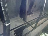
To this end I have created a cabinet to protect these precious items from the elements and road debris. The structure of the cabinet is an angle iron frame which is bolted (and bonded with seam sealant - like Sikaflex but not) to the outriggers, chassis rail and side skirt. The sides and rear were then covered with some aluminium checker plate scraps left over from another project.
When making the frame, the trickest part was getting all the bits to align. I made the one half, bolted that in place and then made cardboard templates and made up the other half. I then also just tacked the pieces together and kept test fitting before the final weld. This was one of the big reasons for it taking so long as I started this part in December last year and gave up during the cold winter.
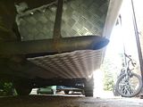
When doing the aluminium side panels, what you can't see is that they come all way to the side skirts. Here I again used the cardboard template technique to make a pattern which I then cut out in aluminium and fitted. The cladding is glued in place with seam sealant and pop-riveted to the frame. The joint with the side skirts is simply glued.
The door/lid/cover is constructed in a similar manner, but from square tubing. For hinges, I had one half of a pair of 'rising' house door hinges, and made the other half out of angle iron and some old 8mm bolts. By doing it this way, the cover is removable for working/inspection, or can just be hinged down for quick access.
TIP: I made the one hinge pin longer than the other so that it is easy to align if you are doing this by yourself. The door is held closed by 2 M6 bolts (I drilled and tapped M6 threads into the frame), I figured this should be pretty safe as I don't want it coming open while driving.
I intend to still line the whole cabinet with Kingspan (or similar). The pipes themselves will get foam covering. I am also considering some form of electric heating elements as has been discussed in the forum. I'm not rushing this part of things as I don't currently intend to venture to really cold climes in the depths of winter, but I would like to find a suitable product at my kind of price (i.e. cheap or free), now where did I put those heated seat elements I removed from the Galaxy seats when making the
Frankenseats......
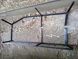
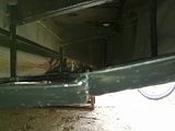
The series of pictures below show the frame in various stages of the construction (I had to make it in two parts and bolt it together to get it under the skirt). These are then followed by pictures of the water system parts and plumbing in place, and finally a couple of pictures of the closed cabinet.
Bare frame before fitting:
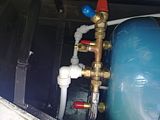
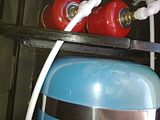
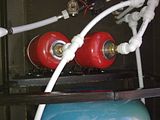
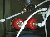
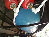
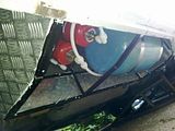
Calorifier, expansion tank and accumulator in place:
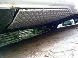
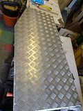
Aluminium cladding:
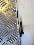
The final product: