
I'm not going to repeat what is available in the RepRap.org wiki, but will paraphrase as a quick introduction.
The RepRap is an open source project to create a self-replicating 3d-printer affordable for the masses. At it's simplest 3d-printer is the type of 'printer' which prints melted plastic into 3d shapes. The current incarnation is the Mendel. All of the plastic parts can be printed on another RepRap or similar, whereas the metal parts, electronics, motors and fixings have to be bought (these are known in the community as vitamins).
The problem lies when you don't have your own RepRap or ready access to one to print the parts for your first Mendel. This is when you have to build a bootstrap device (referred to as a RepStrap). This is a machine which can print in plastic like the RepRap/Mendel, but isn't self replicating. Almost every builder comes up with their own interpretation on this, with some users actually creating very sophisticated systems (see Hydraraptor for an interesting build).
Over the last 3 or 4 months I have been slowly acquiring all the bits to assemble a Mendel, with the plastic now being the main remaining part. I was temped to build an OverlapStrap as built by Giles Bathgate. This attempts to use the same 'vitamins' but with temporary replacement parts for the plastic items. While researching this and deciding what to do I realised that it was difficult to figure out the dimensions of the plastic parts using the drawings and Sketchup. When I posed some questions on the forum yesterday, I was reminded that the WolfStrap would be a good starting point.
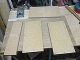
The WolfStrap is a typical Gantry type CNC cartesian bot which can be simply made with DIY materials. Last night after dinner I decided to get started so made off into the garage. Looking at my collection of raw materials (I have lots and odds and sods as I am a bit of a DIY hoarder. I always think I can use something again), I came up with the following:
Dell monitor mechanism is quite intriguing as it comprises a set of mini drawer slides, some bracketry and a spring, string, pully and friction brake mechanism design to overcome the weight of the monitor. It even has 15" and 17" markings imprinted for calibration. I have some more detailed pictures here:
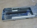
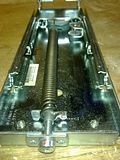
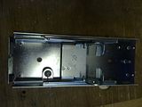
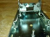
The last two of these are with the weight mechanism removed. I couldn't see the benefit for a RepStrap on which the extruder should be quite light. Probably useful for a mil, but then the 90mm travel will become a limiting factor.
According to the forums, the highest Mendel part is around 30mm, so the 90mm travel that this part will give me should be ample.
The build
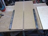
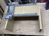
I layed the one chipboard base flat and fitted one of the draw rails on the face but right against the edge so that it extends backwards. Making sure it was straight relative to the edge of the base I screwed it down and then fitted the second rail to the opposite side. For this one I fitted one screw then carefully measured to make sure it was parallel to the first and fitted a second screw to lock it in place.
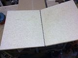
The rails I used have tabs which could be used for locating the deck/base (Y-axis), so I then took the piece of countertop, carefully measured and cut it to fit between the tabs. Before screwing it down I double checked that it moved freely back and forth to ensure that the rails were really parallel.
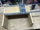
The next step was to make up the gantry. Before starting I took a closer look at the monitor mechanism and realised that if I cut the excess off it, then I would get better clearance without having to make up a long bracket for the extruder. I timmed it off level with the ends of the rails (see the later pictures for clarity).
I then eyed out the second piece of chipboard and figured out that it could be cut into 4 pieces to make the front, back and sides of the gantry. As the two pieces of chipboard were square and indentically sized, this means that the 2 pices cut for the front and back match the width of the base. Fitting the sides to the outsides will square things up nicely.
When cutting the front section, I measured the cutdown Z-axis and used this as the size. The length of the sides was determined by the slot which existed in the piece of chipboard and what was left made up the rear section. I then finished off the gantry frame by screwing and gluing the 4 pieces together.
This is best illustrated by some pictures:
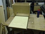
The X & Z axes are just mocked up the picture as is the location of the gantry.
I decided to call it a day at this point as the next step involves two intricate bits of work:
The WolfStrap is a typical Gantry type CNC cartesian bot which can be simply made with DIY materials. Last night after dinner I decided to get started so made off into the garage. Looking at my collection of raw materials (I have lots and odds and sods as I am a bit of a DIY hoarder. I always think I can use something again), I came up with the following:
- The name for my RepStrap - ScrapStrap (as it is made of scrap).
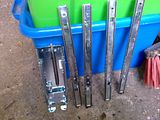
- Two sets of drawer runners from an old flatpack filing cabinet.
- A small sliding mechanism removed from an old Dell PC/Monitor stand. It was designed to allow the vertical height of the monitor to be adjusted.
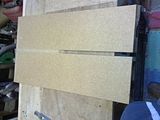
- The 'legs/base' of an old chipboard occassional table (This is type where two rectangular wooden sections with slots it slide into each other to form a +).
- A small piece of lightweight caravan worktop


Dell monitor mechanism is quite intriguing as it comprises a set of mini drawer slides, some bracketry and a spring, string, pully and friction brake mechanism design to overcome the weight of the monitor. It even has 15" and 17" markings imprinted for calibration. I have some more detailed pictures here:


The last two of these are with the weight mechanism removed. I couldn't see the benefit for a RepStrap on which the extruder should be quite light. Probably useful for a mil, but then the 90mm travel will become a limiting factor.
According to the forums, the highest Mendel part is around 30mm, so the 90mm travel that this part will give me should be ample.
The build
I layed the one chipboard base flat and fitted one of the draw rails on the face but right against the edge so that it extends backwards. Making sure it was straight relative to the edge of the base I screwed it down and then fitted the second rail to the opposite side. For this one I fitted one screw then carefully measured to make sure it was parallel to the first and fitted a second screw to lock it in place.
The rails I used have tabs which could be used for locating the deck/base (Y-axis), so I then took the piece of countertop, carefully measured and cut it to fit between the tabs. Before screwing it down I double checked that it moved freely back and forth to ensure that the rails were really parallel.

The next step was to make up the gantry. Before starting I took a closer look at the monitor mechanism and realised that if I cut the excess off it, then I would get better clearance without having to make up a long bracket for the extruder. I timmed it off level with the ends of the rails (see the later pictures for clarity).
I then eyed out the second piece of chipboard and figured out that it could be cut into 4 pieces to make the front, back and sides of the gantry. As the two pieces of chipboard were square and indentically sized, this means that the 2 pices cut for the front and back match the width of the base. Fitting the sides to the outsides will square things up nicely.
When cutting the front section, I measured the cutdown Z-axis and used this as the size. The length of the sides was determined by the slot which existed in the piece of chipboard and what was left made up the rear section. I then finished off the gantry frame by screwing and gluing the 4 pieces together.
This is best illustrated by some pictures:


The X & Z axes are just mocked up the picture as is the location of the gantry.
I decided to call it a day at this point as the next step involves two intricate bits of work:
- Fitting the X & Z-axes.
- These need to be both parallel as a set (easy on the Z-axis as it is a unit), as well as perpendicular to the other axes
- I am thinking about how to achieve this accurately, no decisions yet
- Figuring out and fitting the drive mechanism.
- The WolfStrap uses threaded rod (aka studding, aka allthread).
- The alternative is belt drive, but this requires pulleys. I do have some out of some scrap printers which may work.
- The WolfStrap uses threaded rod (aka studding, aka allthread).


Use pulleys, with threaded rod it will take you forever to create a set of RP parts for a Mendel.
ReplyDeleteBob,
ReplyDeleteAgreed, it's about making sure I have the pulleys (without the ability to print them). I'll have adig tonight as I recently scrapped a plan printer which had quite a long length of belt and matching pulleys/
I am with Craig on that one, Threaded drives are easier when you start out, because they are easier to make and because the speed is slower, which makes it easier to control. Print some pulleys then upgrade. Thats what I am doing
ReplyDeletehttp://www.gilesbathgate.com/category/reprap
By the way, to get the dimentions of the STL parts you can use OpenSCAD to import the stl's using import_stl(); and then you can use project(); to project them onto a 2D plane, and finally export them to DXF. Once in DXF format they can be opened in QCad and dimentions measured and/or printed onto paper. I think I shall write a post about this I assumed it was common knowlege.
ReplyDeleteGiles,
ReplyDeleteThanks for the input. Please do write that article. I haven't used CAD in years (I used AutoCAD during engineering back at university), but don't have the time to dedicate so tend to take an Agile approach (I'm a software developer now), i.e. learn as much as I need to get the job done and ask lots of questions.
Looking like you have a good start towards your scrapstrap!
ReplyDeleteNice blog, plenty of pictures. good luck with your build!
http://www.gilesbathgate.com/2010/06/extracting-2d-mendel-outlines-using-openscad/
ReplyDelete@Renoir: Thanks. I've made some more progress, but not enough to blog about. Watching football tonight.
ReplyDelete@Giles: Thanks, I'll check that out.
What did you do for the electronics?
ReplyDeleteI've got a load of old stuff at home and I'm contenmplating using it to build a repstrap.
Amongst them I have some Pic 16f627, which I've used to drive two stepper motors before but I'm unsure how to interface them with a Computer.
If the software outputs via a parallel port I think I could do that, but if not, then I'd be stuck.
How did you get around that?
-Andy -S-
Hi Andy, thanks for the interest. I bought eleconics, it was the frame I was building fro. Scrap. It all kind of worked,but the z axis was binding and eventually I got fed up and bought the plastic pieces from nophead
ReplyDelete