I'd like to start by thanking Stevitee for posting his photo sequence on the Mercedes Club forums. Without those pictures I'm sure it would have taken me a lot longer as I didn't have to figure everything out, I simply had to go through the motions. So here goes:
Before
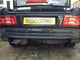
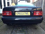
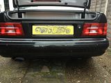
Here are some quick "Before" shots for later comparison
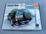
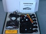
I bought one of the multitude of kits available on the internet (or eBay). These came branded as Gadgetman, but the sensors are identical to those in a kit I bought for the ambulance so expect it's the same factory in China making them all.
I chose the 6 sensor (2 front 4 rear) kit with a buzzer as I didn't want to mess up the interior with an after-market display (I had one in a cheap runabout I'd bought and it didn't suit the interior).
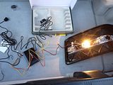
I took the time to quickly test the kit and all the sensors before taking my car apart. Just in case I needed to return anything.
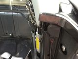
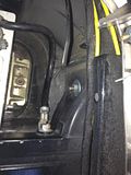
Rear bumper removal is up next. The bumper is held in place by 2 bolts (13mm nuts) which come through the rear of the vehicle. These nuts need to be completely removed. The following two pictures show the location of the these nuts (right and left side of the vehicle respectively).
In addition the side extensions of the bumper slide over a plastic fittings which are held on with 2 x 10mm nuts each. The two on the side where the battery is located can be loosened without removing the battery, but it would be much easier with the battery out. These don't have to be removed entirely (in fact I'd advise against it), but loosening them helps with wiggling the bumper about. Again pictures of the right and left sides respectively.
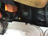
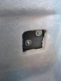
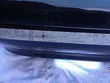
Before removing the bumper I stuck on some masking tape (see picture below) and figured out where I thought the sensors would go. I centred them vertically on the bumper "insert" (it isn't really an insert but it looks like one), and initially measured them out to be evenly spaced across the back of the bumper (see later why I say initially).
The second picture below is of the wheel arch liner. This is easy to prise out gently when the 2 x 10mm nuts hold the extensions tight have been slackened. Also be very careful as there are lugs (you can just make the one out if you know what to look for in the picture below - which you probably won't if you're reading this) at the top front of each extension which hold the bumper in place. (Thanks to numerous posts on the forums I knew about these and didn't break mine as many did).
Bumper off


Bumper off
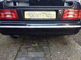
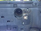
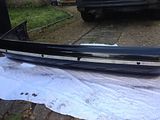
My 9 year son was helping me with this job. We carefully pulled the bumper off and laid it on an old blanket. Some pictures below of the bumper off and the grommet (middle right of the car) that I chose to put my wiring through. In retrospect I should have put it through the one at the middle left as the wiring runs along the left hand side of the car, but there was ample length in the wires.
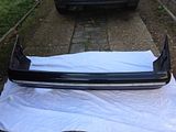
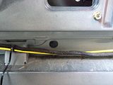
Let the holes begin


Let the holes begin
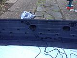
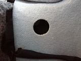
Here you can see that I followed Stevitee's suggestion of drilling a pilot hole. The supplied hole saw has a 4.5 mm centre bit so I used the same to drill the pilot holes. Here you will also be able to see that at the rear of the bumper are 4 recessed in the polystyrene packing which appear factory made for parking sensors. This is why I earlier mentioned having marked out evenly space holes. when I noted these recesses I moved the sensors so that they would be centred in these recesses.
Fitting the rear sensors


Fitting the rear sensors
I fitted the supplied angle rings to the sensors and fitted the sensors with the thin side to the top. this angles the sensors away from the ground. This decision was made based on the instructions talking about the sensors not pointing at the ground. I suspect that in this bumper the rings cold be omitted, but better safe than sorry.
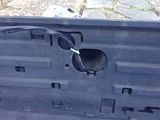
If you look at the pictures below you will note that I was able to thread the sensor wires behind the plastic backing which makes quite a need job. I also took the time to fit some heat-shrink sleeving over the 4 sensor wires so they would go through the grommet as one. Subsequent re-fitting of the bumper truly followed the Haynes principle of being a reversal of the removal procedure. I did however make sure that it was properly lifted and pushed in before tightening, so an assistant does come in handy.
Stripping the interior


Stripping the interior
having followed Stevitee's approach I knew that it would be possible to route the front sensor wires through to the boot from the engine compartment via the sill, so I proceeded to take the interior apart.
The following pictures are of the sill cover fixings; when these 2 have been removed the cover simply pulls off.
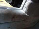
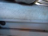
You don't need to remove the carpeted cover under the dash. I wasnt' sure and loosened the 2 8mm screws and discovered that someone had been there previously and actually broken it. I put the 8mm screws back and it isn't noticeable, but now I'll never forget it.
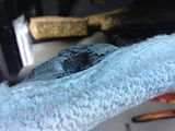
To feed the wires through from the engine compartment the easiest is to feed them through the grommet that the bonnet release cable goes through. To get at this you need to remove the left side kick board. Once the sill cover has been removed, this is held in place by the 8mm screw that holds the bonnet release handle in place. Remove that and then slide the kick plate backwards (I didn't realise this so damaged the tab on mine as I thought it would be held in by the standard press fit panel fasteners).
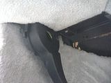
Fitting the front sensors


You don't need to remove the carpeted cover under the dash. I wasnt' sure and loosened the 2 8mm screws and discovered that someone had been there previously and actually broken it. I put the 8mm screws back and it isn't noticeable, but now I'll never forget it.

To feed the wires through from the engine compartment the easiest is to feed them through the grommet that the bonnet release cable goes through. To get at this you need to remove the left side kick board. Once the sill cover has been removed, this is held in place by the 8mm screw that holds the bonnet release handle in place. Remove that and then slide the kick plate backwards (I didn't realise this so damaged the tab on mine as I thought it would be held in by the standard press fit panel fasteners).


Fitting the front sensors
Again following Stevitee's procedure I decided the fit the front sensors without removing the bumper.
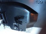
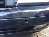
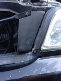
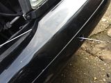
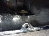
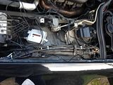
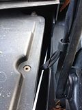
Some careful measuring and drilling later I had two holes in the bumper, right into the polystyrene packing (picture 1). Removal of the plastic air duct (picture 2) and slacking off the bumper retaining nuts (picture 4) allowed me enough room to shove a piece of coat hanger wire through the polystyrene from the back (picture 3). It goes through OK, but needs a bit of time.
I then tape the sensor wire to this and pulled it back through. Having learnt my lesson on the first one (I damaged the wire), on the second I first pulled through a double piece of coat hanger wire to force the hole bigger before pulling the sensor wire through.
Routing the wires


Routing the wires
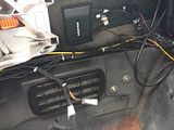
Routing the front wires back to the boot starts in the engine bay by feeding them along the left side of the engine compartment. There is a convenient plastic wire trunking fitting here. In the second picture you can see the coat hanger wire having been pushed through bonnet release cable grommet from the passenger foot-well. I then used this to pull the wires through.
Stripping the rear seat area


Stripping the rear seat area
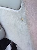
My car has rear seats, so the whole base and back rest on the left side of the car have to come out. This then allows the carpeted panel to be removed. (I noted that the plastic screw cover had been glued in on mine so broke on remove). This reveals more plastic trunking that the wires can be threaded through into the boot. At the same time I threaded the buzzer wire through and hid the buzzer behind the panel so it is inside the passenger compartment.

Control box


Control box
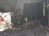
The final step was to wire up and install the control box. The sensors and buzzer all simply plug in, but I had to solder the power leads to the brake and reversing light fittings for the front and rear sensors respectively. I was able to wire the earth lead an existing earth point near the aerial.





No comments:
Post a Comment